Electronic Symbols Chart

Electronic symbols chart
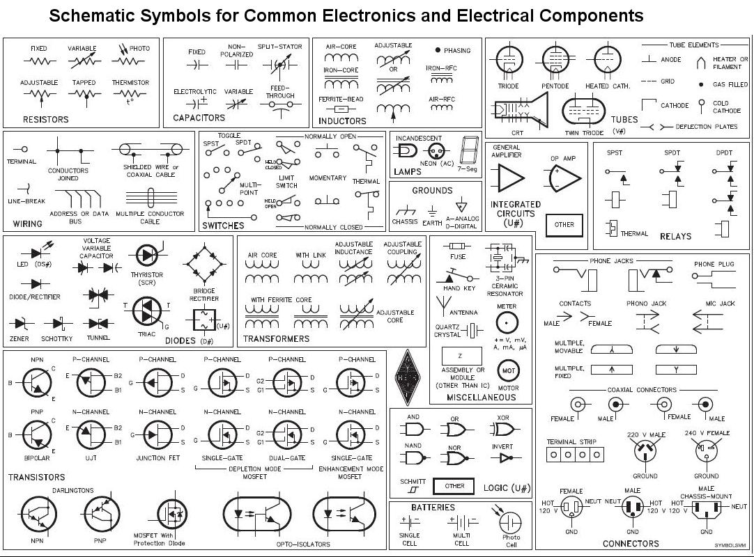
10 common electrical symbols found on electrical schematic...
<ul class="i8Z77e"><li class="TrT0Xe">Phase Meter.</li><li class="TrT0Xe">240V Outlet.</li><li class="TrT0Xe">Flow Switch.</li><li class="TrT0Xe">NOR Gate.</li><li class="TrT0Xe">Continuously Adjustable Resistor.</li><li class="TrT0Xe">Normally open foot switch.</li><li class="TrT0Xe">Timer off delay, normally open.</li><li class="TrT0Xe">Shielded transformer with magnetic core.</li></ul>What are the symbols used in electrical?
| Name | Description |
|---|---|
| Electrical Wire | It is the symbol that is used to represent a wire. |
| Connected Wires | This Symbol represents the wire connected crossing. |
| Not Connect Wires | This Symbol shows that wires are not connected on crossing. |
What do electronic symbols mean?
Electrical symbols are a graphical representation of basic electrical and electronic devices or components. These Symbols are used in circuit and electrical diagrams to recognize a component. It is also called a schematic symbol. Each component has typical functionality according to its operational characteristics.
What are the most common circuit symbols?
Below is an overview of the most used symbols in circuit diagrams.
- Battery. The symbol for a battery is shown below.
- Resistor. The schematic symbol of the resistor are drawn in two different ways. ...
- Potentiometer. ...
- Schematic Symbols of a Transistor. ...
- Schematic Symbol for an Integrated Circuit. ...
- Logic Gates. ...
- Inductor. ...
- Transformer.
How do you read electrical symbols?
You see a three-phase ac electric motor symbol. Here this font is the symbol for a solenoid valve.
What is the symbol for voltage?
Voltage is measured in volts. The symbol for volts is V. Current is how much electricity is flowing through the circuit.
What are the 5 types of wiring diagram?
6.2: Types of Electrical Diagrams
- Schematic Diagrams.
- Wiring diagrams.
- Block diagrams.
- Pictorial diagrams.
What is the name of electronic symbol?
An electronic symbol is a pictogram used to represent various electrical and electronic devices or functions, such as wires, batteries, resistors, and transistors, in a schematic diagram of an electrical or electronic circuit.
What is the symbol for current?
Current is usually denoted by the symbol I. Ohm's law relates the current flowing through a conductor to the voltage V and resistance R; that is, V = IR.
Why are electronic symbols important?
Electronic symbols are mainly used for shortening the drafting as well as to understand the circuit diagram. These symbols are identical throughout the industry. The addition of a dot, line, letters, shading & numbers provides an exact meaning of a symbol.
Why are electrical symbols important?
Electrical symbols are required to do the electrical drawing and without the help of electrical symbols, we won't be able to do the electrical drawing. Electrical circuits are represented by electrical drawings. Symbols and number combinations are used to represent electrical circuits.
Why are circuit symbols used?
Circuit symbols are used because they convey in the most elemental manner what a component does, not what it looks like. Components have thousands of variations in packaging; the reader is not interested in what the actual part looks like, but how it works with other circuit elements to form a circuit.
What is a resistor symbol?
The ohm (symbol: Ω) is the SI unit of electrical resistance, named after Georg Simon Ohm. An ohm is equivalent to a volt per ampere.
What does Z mean on a circuit board?
X: crystal, ceramic resonator. XMER: transformer. XTAL: crystal. Z: zener diode.
How many circuit symbols are there?
The database includes around 1750 circuit symbols overall. ANSI standard Y32: This standard for electronic component symbols is the American one and is also known as IEEE Std 315. This IEEE standard for circuit symbols has various release dates.
How do you read electrical wires?
First of all, there is a rule of thumb in standard wiring diagrams that you should read the diagram from left to right and from top-down. Exactly like reading a book! But sometimes, designers make some exceptions to have a better layout such as this page.
What are the different schematic symbols?
Schematic Symbols
- Wires (Connected) This symbol represents a shared electrical connection between two components.
- Wires (Not Connected) ...
- DC Supply Voltage. ...
- Ground. ...
- No Connection (nc) ...
- Resistor. ...
- Capacitor, Polarized (Electrolytic) ...
- Light-Emitting Diode (LED)
What is electrical wiring diagram?
A wiring diagram shows the relative layout of the components and the wire connections between them. This type of diagram shows the physical relation of all devices in the system, the conductor terminations between these devices, and are commonly used in motor control installations.
What are the 3 Ohm's law?
3-4: A circle diagram to help in memorizing the Ohm's Law formulas V = IR, I = V/R, and R= V/I.
What is current unit?
The SI unit of current is ampere which measures the flow of electric charge across a surface at the rate of one coulomb per second. Since the charge is measured in coulombs and time in seconds, so the unit is coulomb/Sec (C/s) or amp.
15 Electronic symbols chart Images
Basic electronic symbols

Gm Wiring Diagram Legend Electrical symbols Electrical wiring Home

Electronic Components Circuit Symbol Electrical Symbols Circuit

Electronic electrical symbols Electronic circuit projects
Electronics on Pinterest Arduino Electrical Engineering and Led

Digital Electronic Symbols Electrical diagram Electrical symbols

14 Electronic ideas electronics circuit electrical symbols

17 Best images about auto elect motors on Pinterest The alphabet

electrical symbol chart Electrical symbols Electronic schematics

Logos of Electronic Component Manufacturers

Electrical Symbols Electronic Symbols in PDF Electrical symbols

1000 images about Electrical Components on Pinterest Types of Block

Common electronics component schematic symbols Electrical symbols

the electronic and electronic symbols website is displayed in this
Post a Comment for "Electronic Symbols Chart"